Precipitation Hardening Model with Multiple Particle Groups
The calculation of precipitation strengthening σP in Eq. 10 can be extended to multiple particle groups with different strengthening mechanism.
|
|
Where g is the size group defined by a particle size range and fg is the volume fraction of the group. j is the strengthening mechanism in each size group. is the weight fraction of the mechanism with RC the critical radius for transition from one mechanism to another.
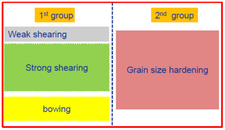
Figure 1: Schematic plot for strengthening groups
As an example shown in Figure 1, the first group has three mechanisms “weak shearing”, “strong shearing” and “bowing” while the second group has only one mechanism. This is very typical in the γ' strengthened Ni-based superalloys. The big primary γ' acts to limit grain growth during solution treatment and enhances grain boundary strengthening while the tertiary/secondary γ' particles strengthen materials through the weak/strong shearing and bowing mechanisms. In [2015Gal], Galindo-Nava proposed a unified model for weak/strong shearing and bowing mechanisms. The transitions from weak to strong shearing and to bowing are automatically taken care. The unified critical resolved shear stress τshearing is calculated as,
|
|
where l1 is the length of the leading dislocation cutting the precipitates and defined as,
|
|
with the critical radius defined as,
|
|
where μ is the shear modulus and b is the magnitude of the Burgers vector. In Eq. 2, the mean distance is given by
with
and
.
The Orowan yield stress is given by,
|
|
where M is the Taylor orientation factor. The total yield strengthen due to precipitation hardening can be calculated by Eq. 1.
